Final Project
For this module, the final project that I have decided to do is a stream deck, which is basically a macropad that execute keyboard commands and/or shortcuts but these commmands/shortcuts are specific to streaming purposes, such as to swtich between scenes or play a sound.
PCB Design
Although this was where my journey started, it was also where it ended. More details will be revealed later. For the PCB design, I was very unsure and confused as I lacked knowledge on the microcontroller chips that the Fablab had to offer. As my stream deck will be connected to the computer, usb compatability had to be there in order for it to work in the first place. However, the microcontrollers did not have any hardware usb compatability. This was where the workaround came in. There were two ways to get usb compatability. I went with the first, which is to use v-usb, a software-only implementation of a low-speed USB device for Atmel's AVR® microcontrollers, making it possible to build USB hardware with almost any AVR® microcontroller, not requiring any additional chip. The microcontroller that I ended up using was the ATMega328.
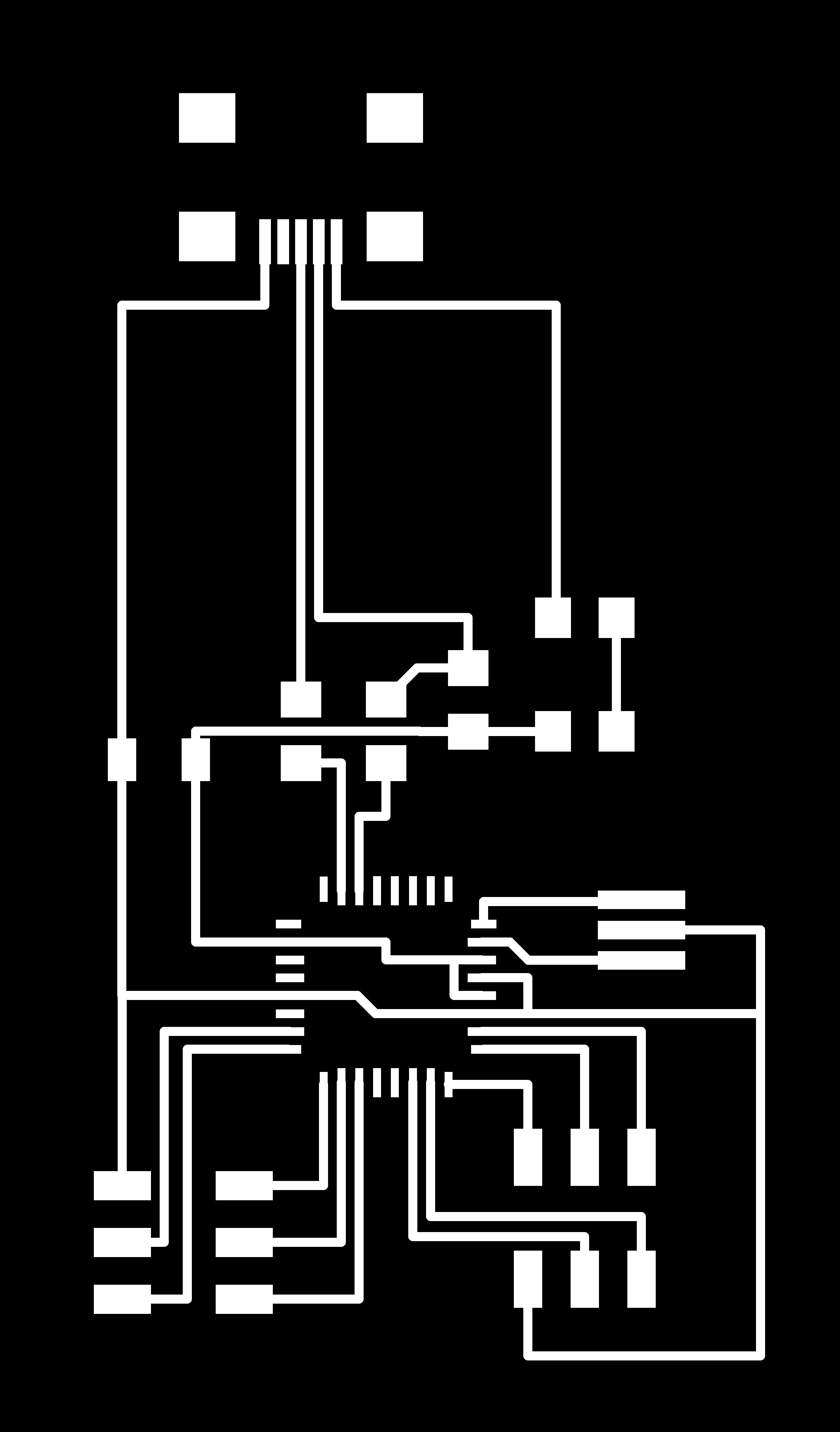
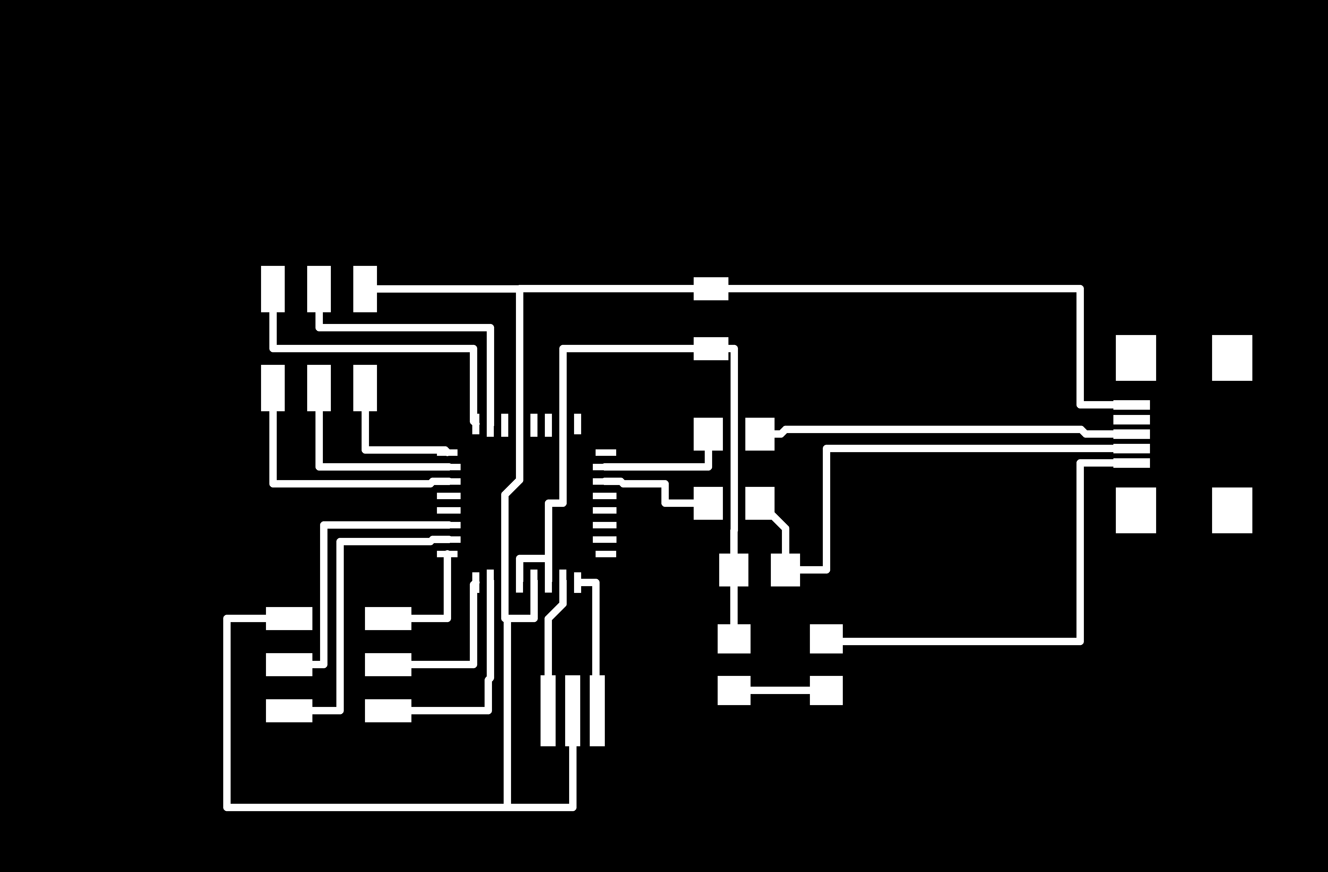
My intended design of the PCB was to use ISP headers as placeholders for the connection pads to be cut out when milling, so that I can directly wire the switches to the board. Combine that with the HID Keys basic circuit layout, a resonator as we did not use crystals, we have the entire circuit.
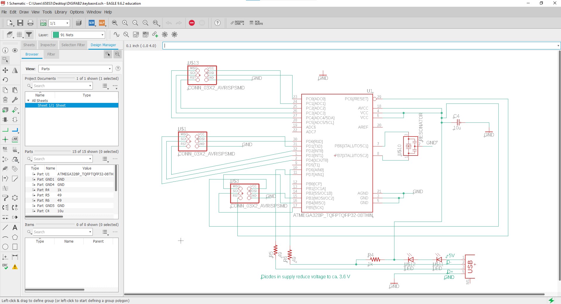
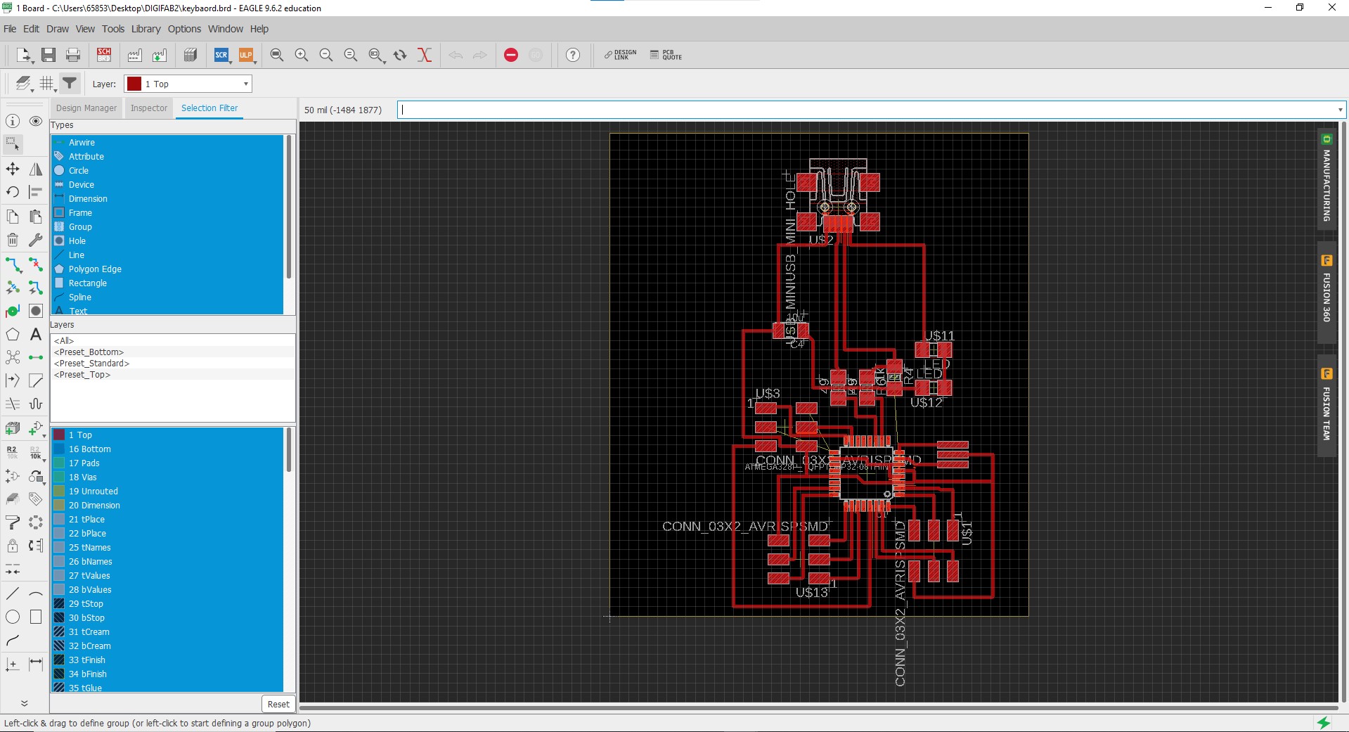
The board had some issues at first, as the components were taking up more space than it should. With the help of my lecturer, the board was redesigned and rearranged to take up less space and make it more compact.
At this point in time, I thought that I was all good to go. I readied up the PCB gcode and milled out a successful clean board. I even soldered on all the important components first before I realised I had made a few huge mistakes. One major mistake that I made was not considering how was I going to program the board. The ISP header connections were not connected to the right pins on the ATMega328 at all and this made it such that the microcontroller was not programmable. This led me to hard wire the connections instead, stretching and connecting wires across the board, making it very messy. Second mistake was that the D+ and D- pins of the USB header were not connected to the right pins, the current connection was incorrect in such a way that the USB header was not dectable at all. Noticing all these mistakes, another board was created.
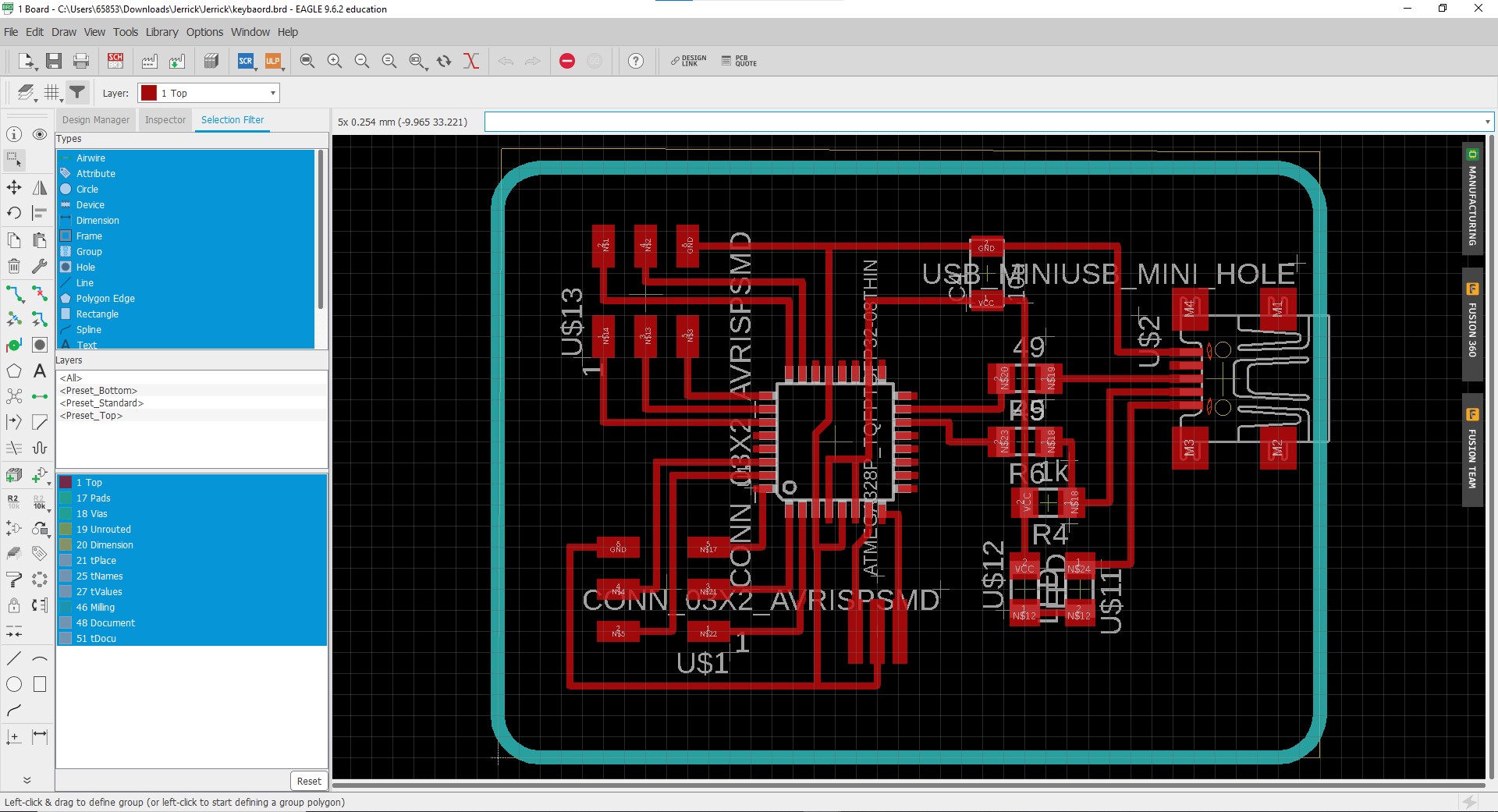
Lynn, my classmate, helped me a lot from this point onward as his project was similar to mine. This new board was also mostly due to his efforts.
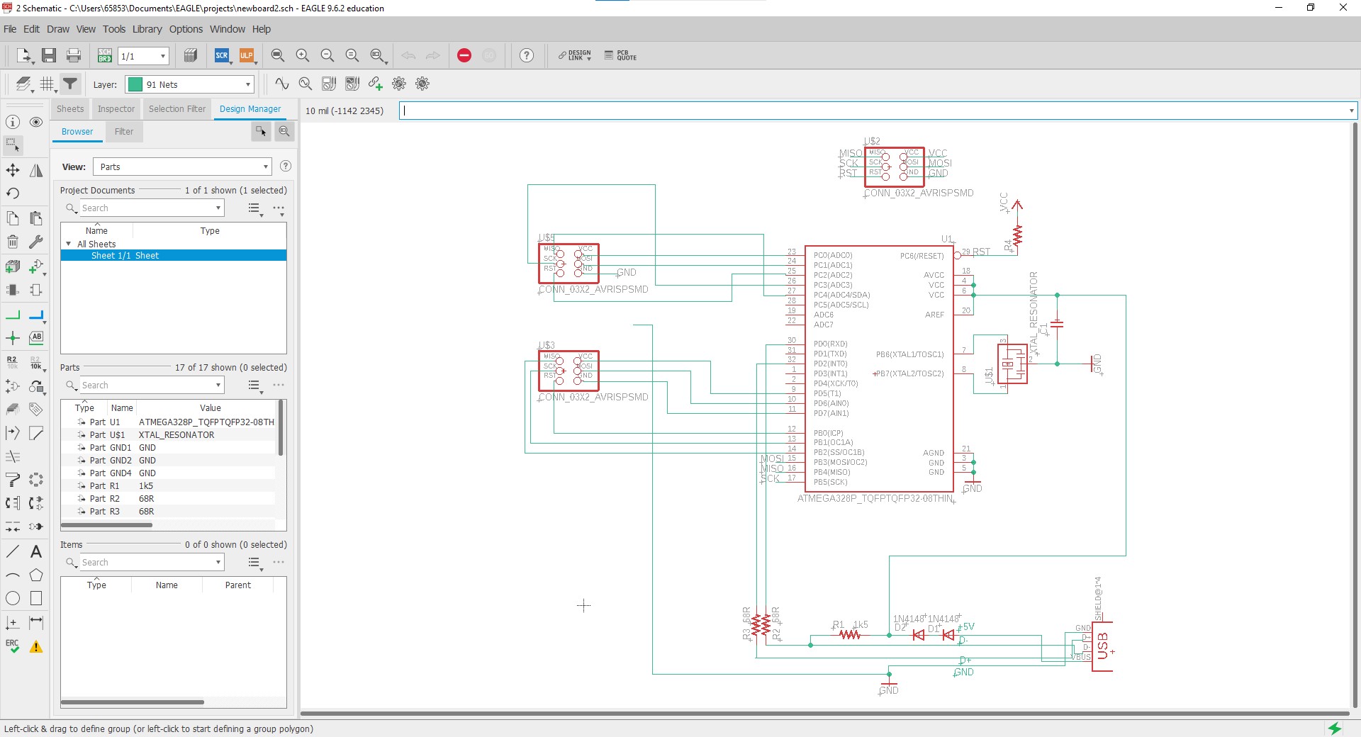
After all the repeated failures before this board, this seemed to hold more promise in working out succesfully. It was time to move on to the milling of the PCB.
PCB Machining
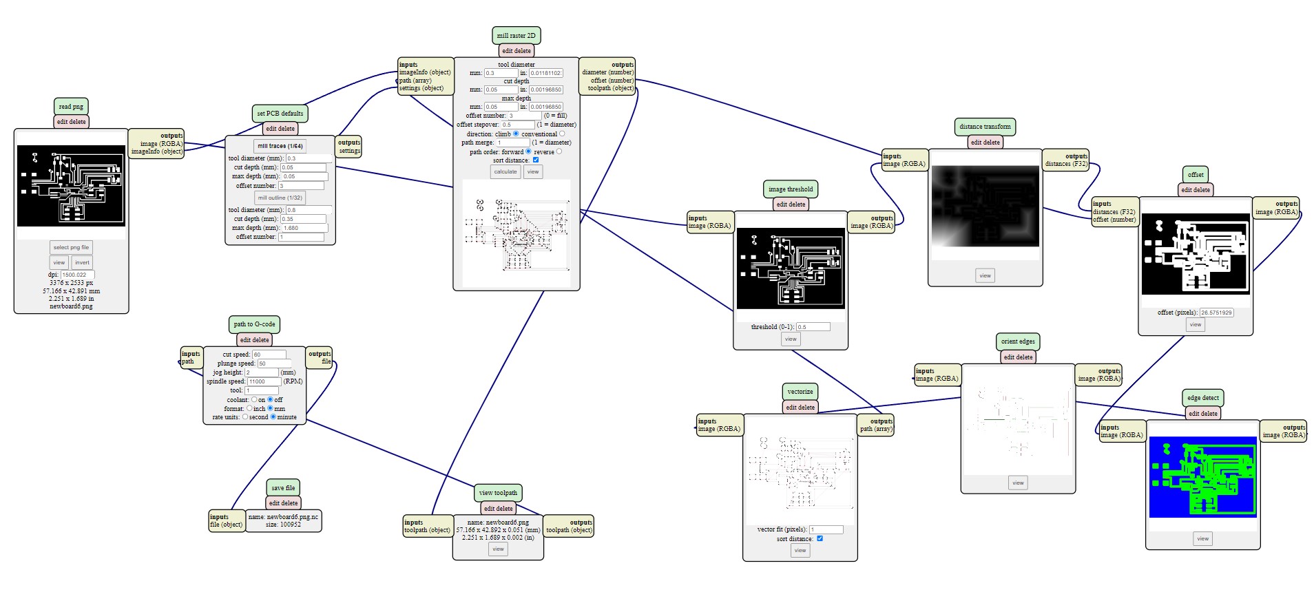
As usual, the program that I used to generate all my PCB gcodes is mods. All the gcodes I created are generally the same settings, except that I tweaked the tool diameter a few times just to see how thin in needs to be in order to get all the traces out just right.
Here are the previous boards that did not work
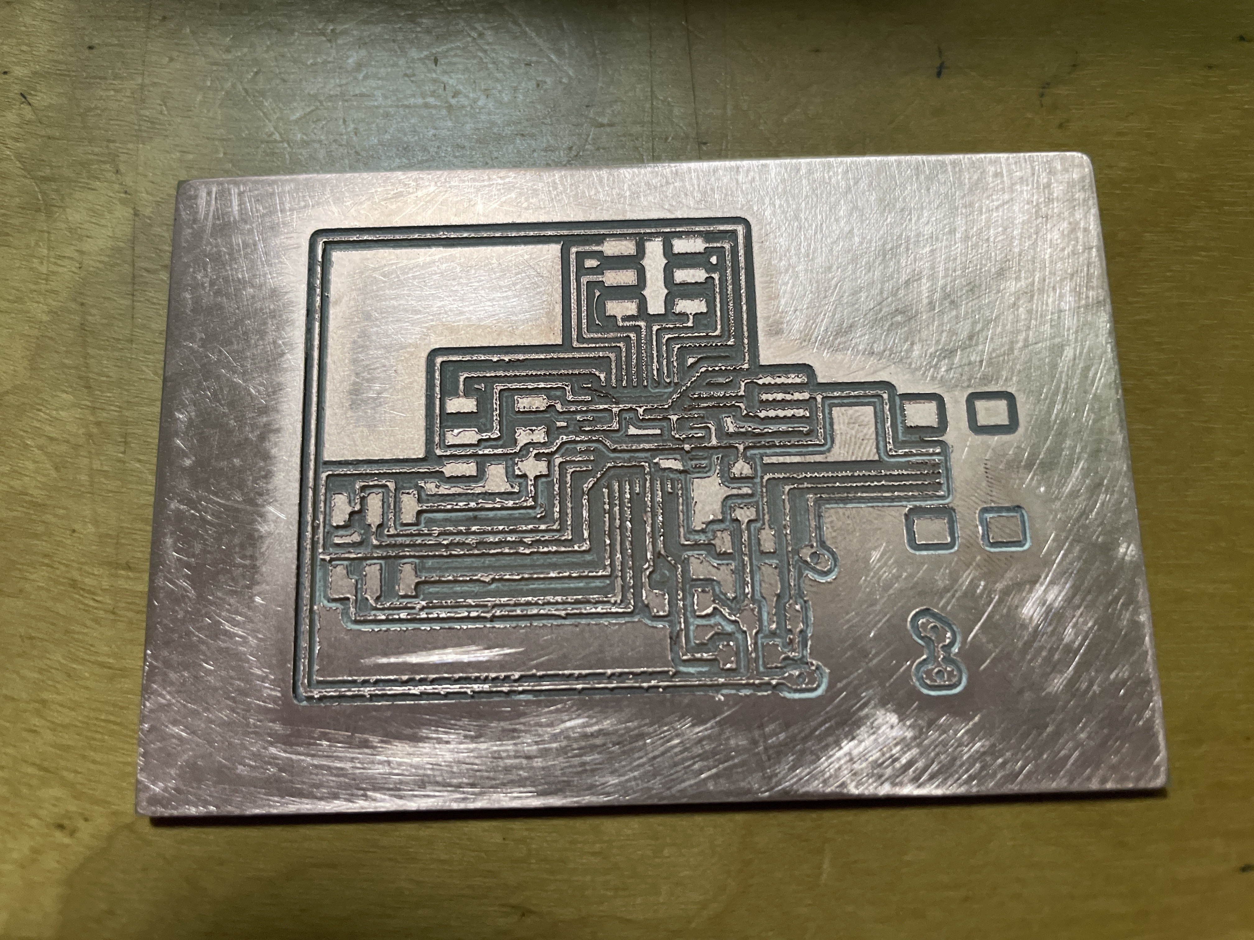
After configuring the settings in mods, this is the result I got.
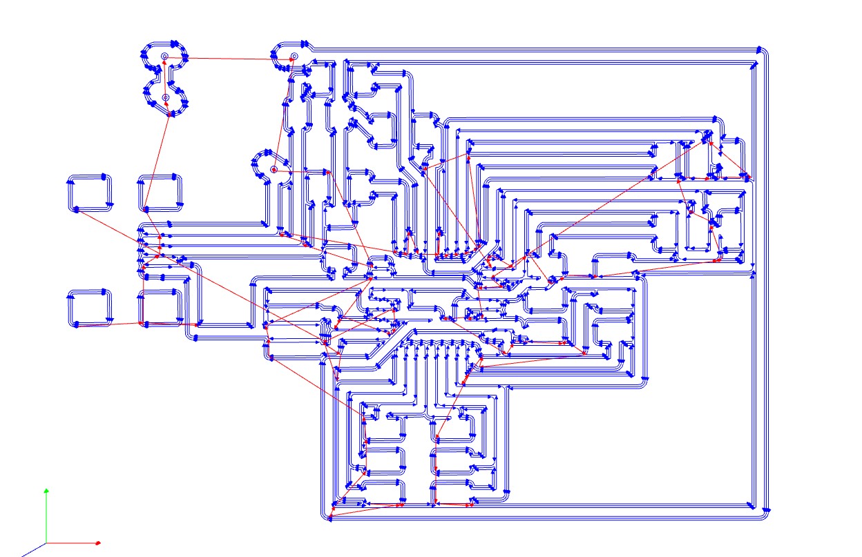
Now that I have my gcode, I was ready to mill the PCB out. Before the attempt to mill this new board, I already had many past attempts on milling the previous boards, many of which failed. Here are most of them.
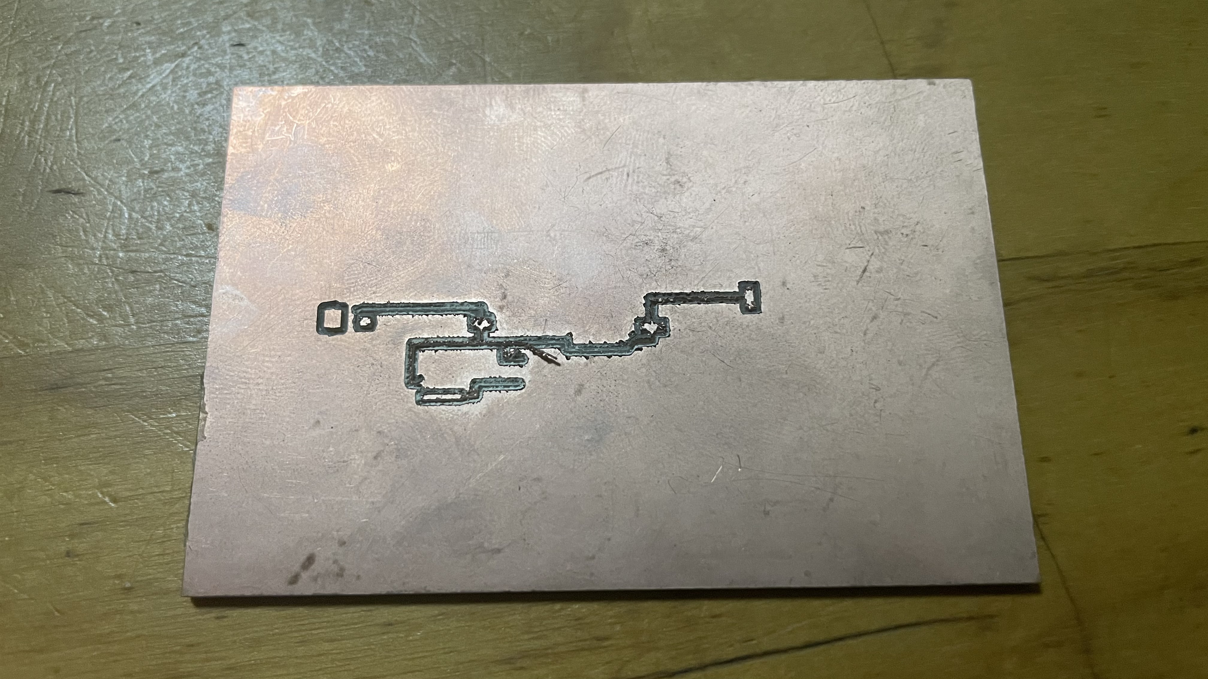
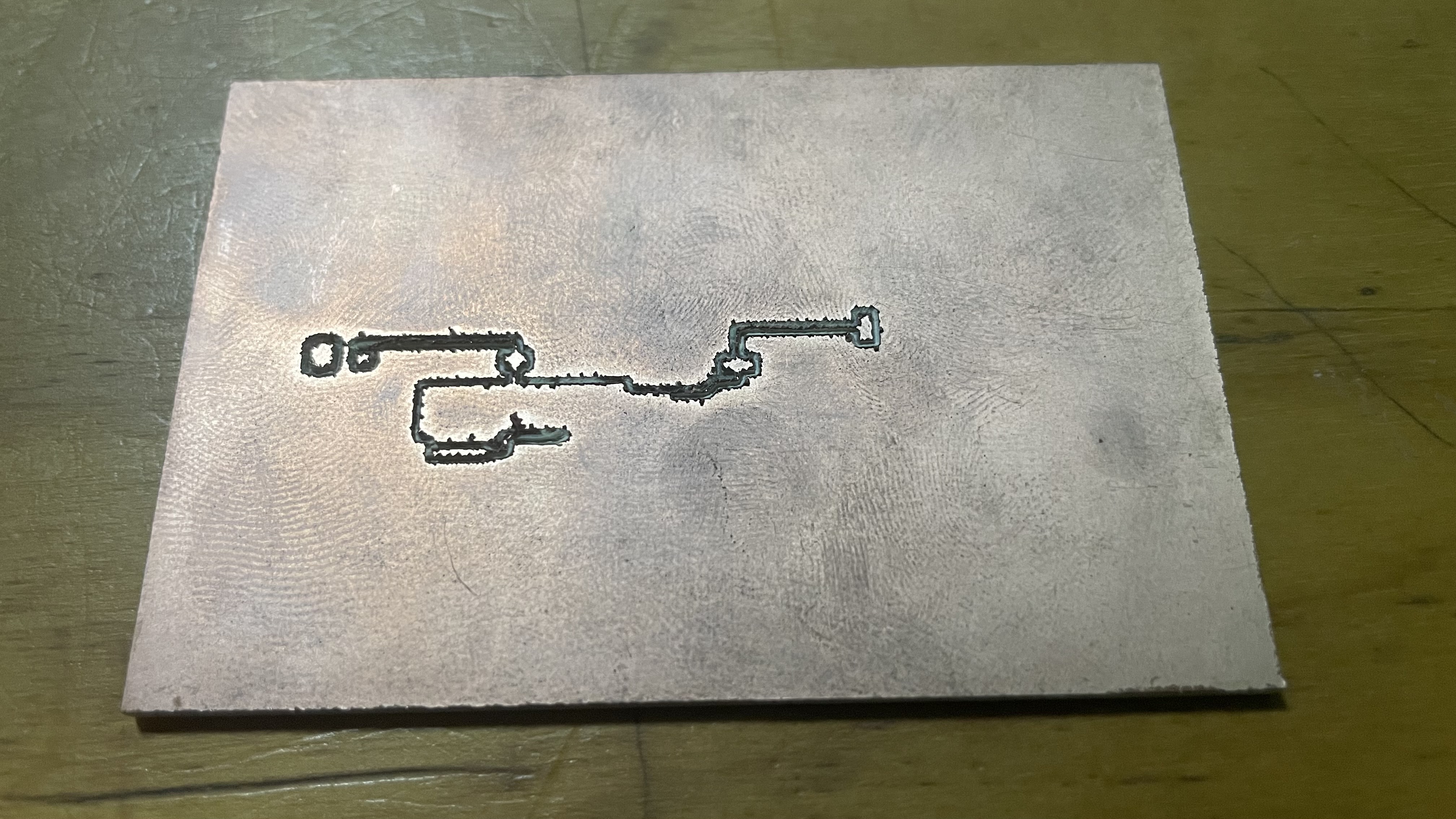
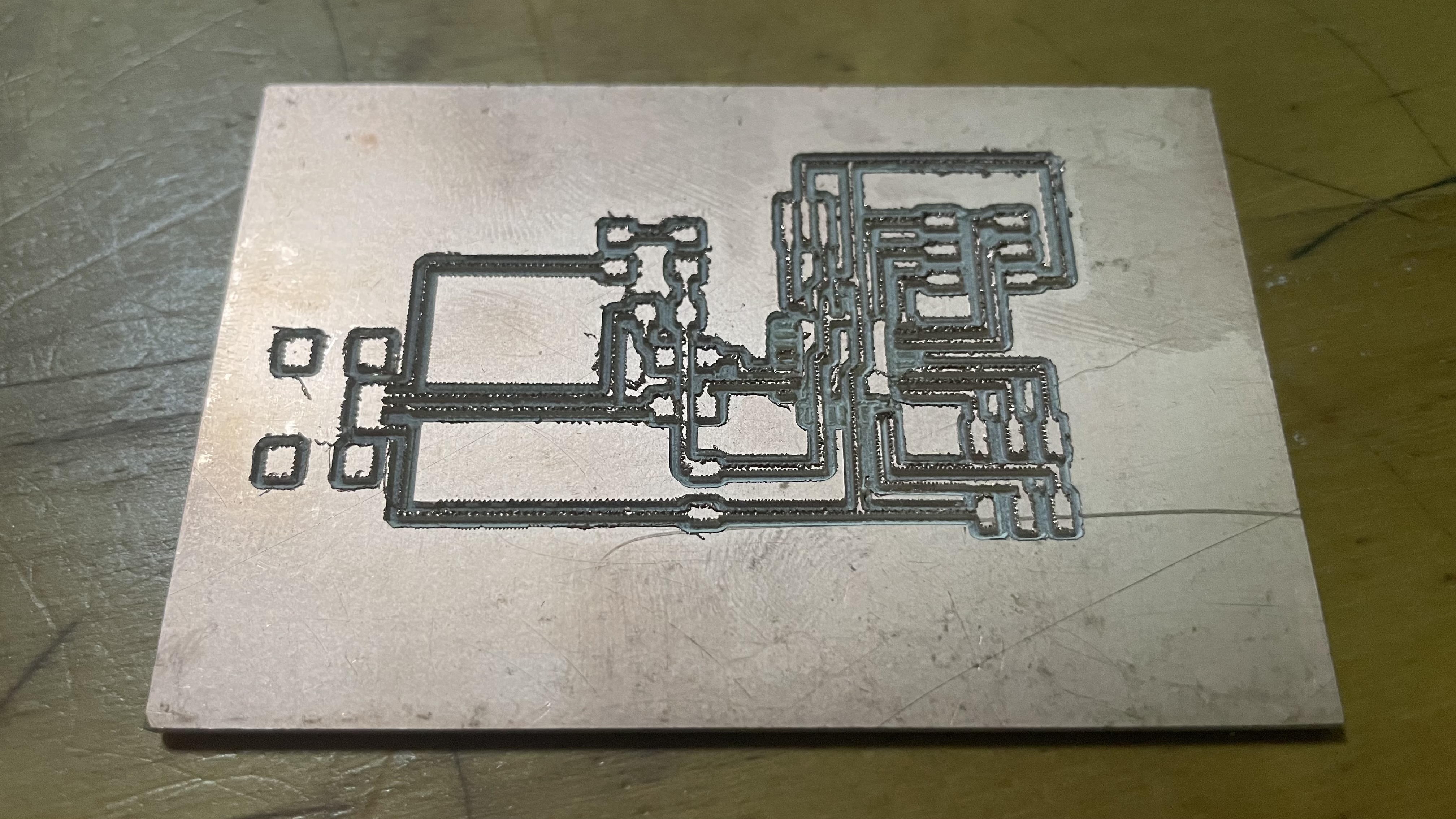
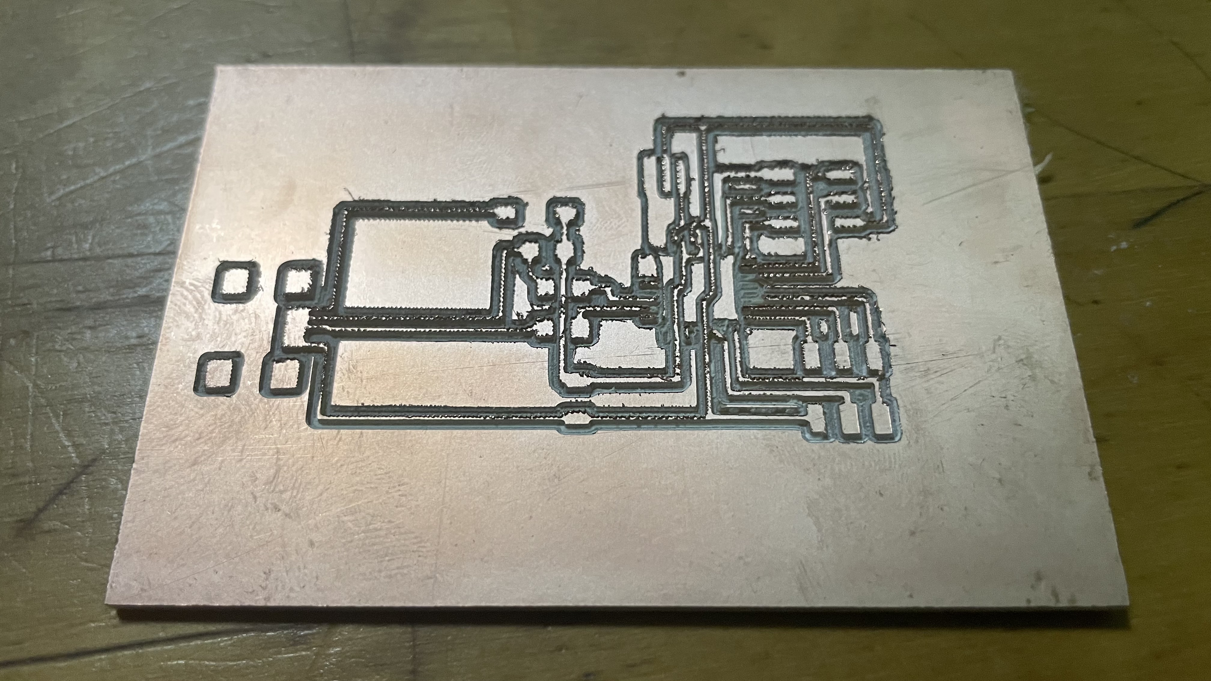
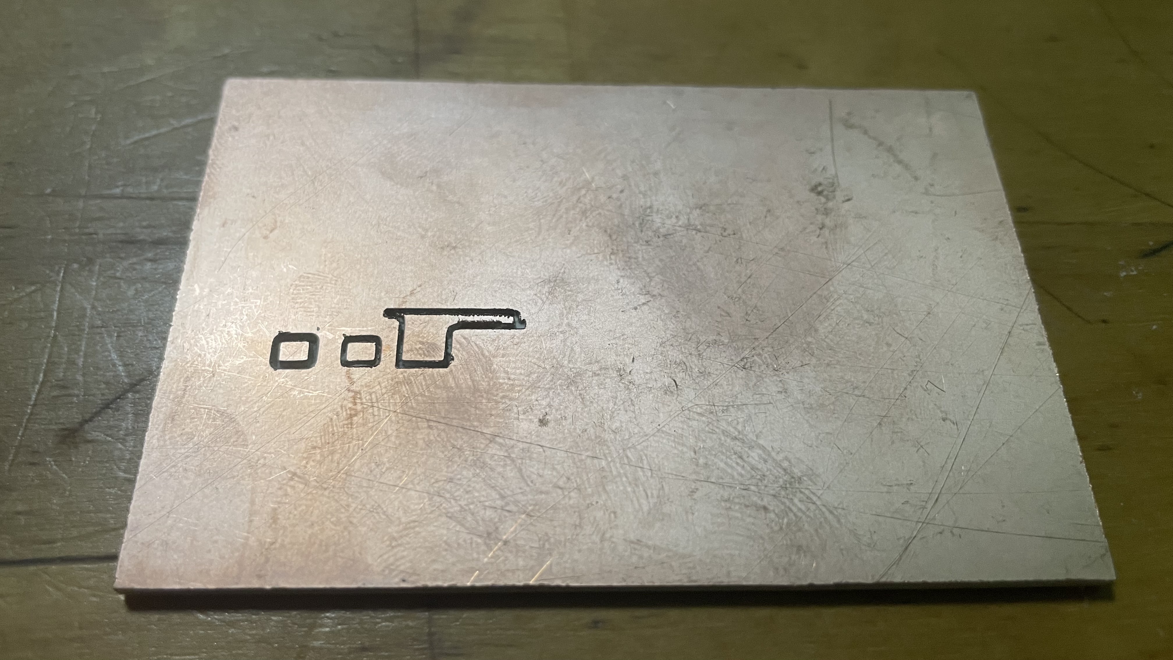
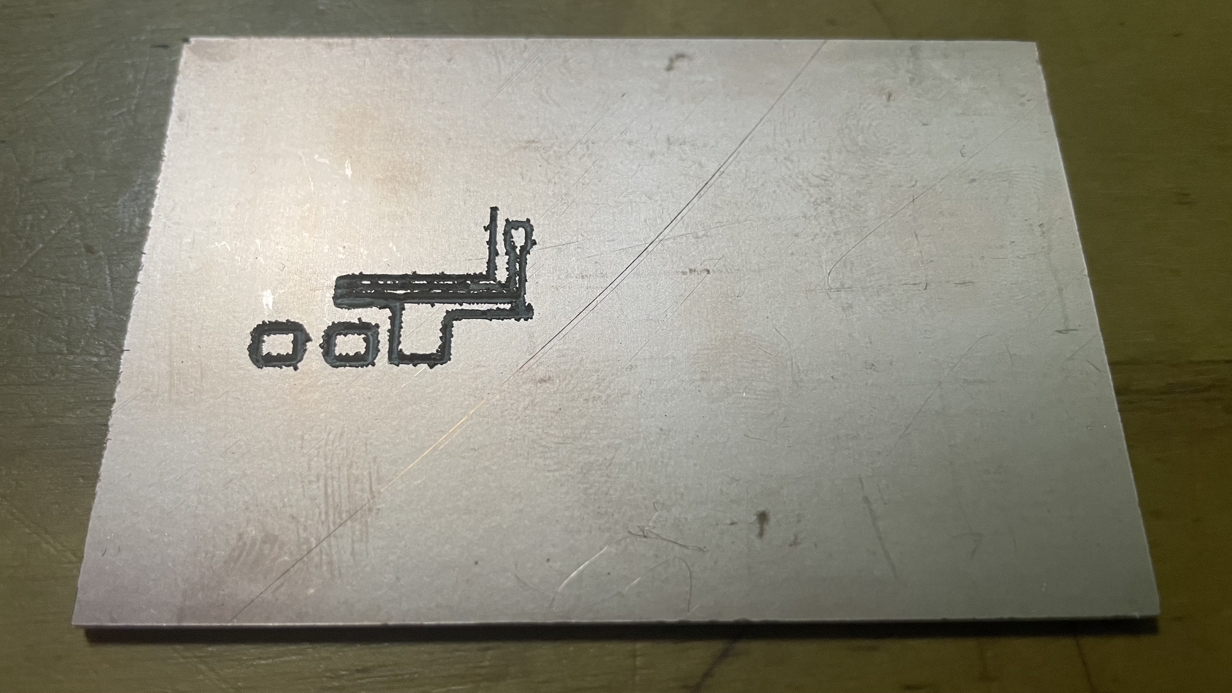
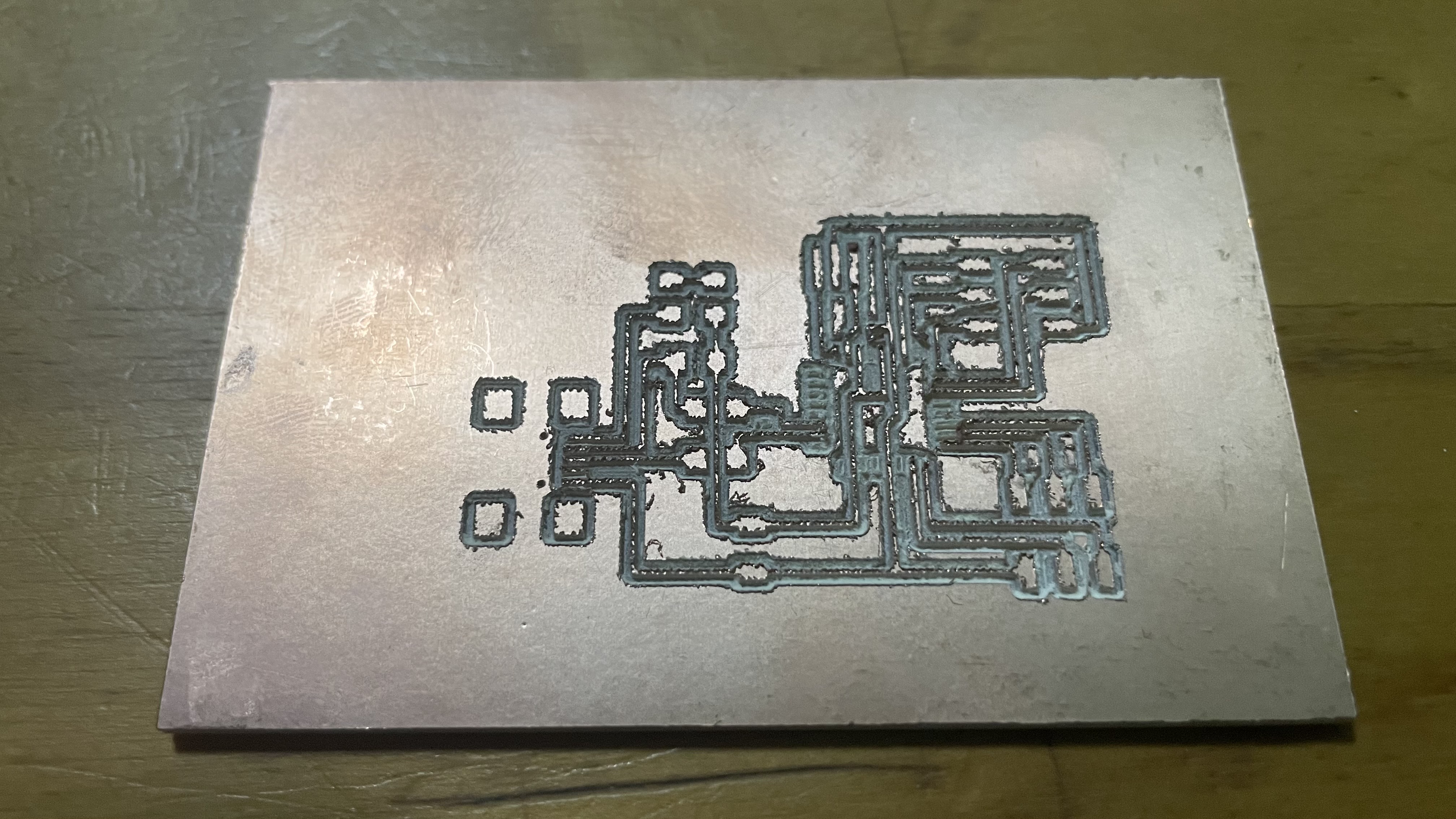
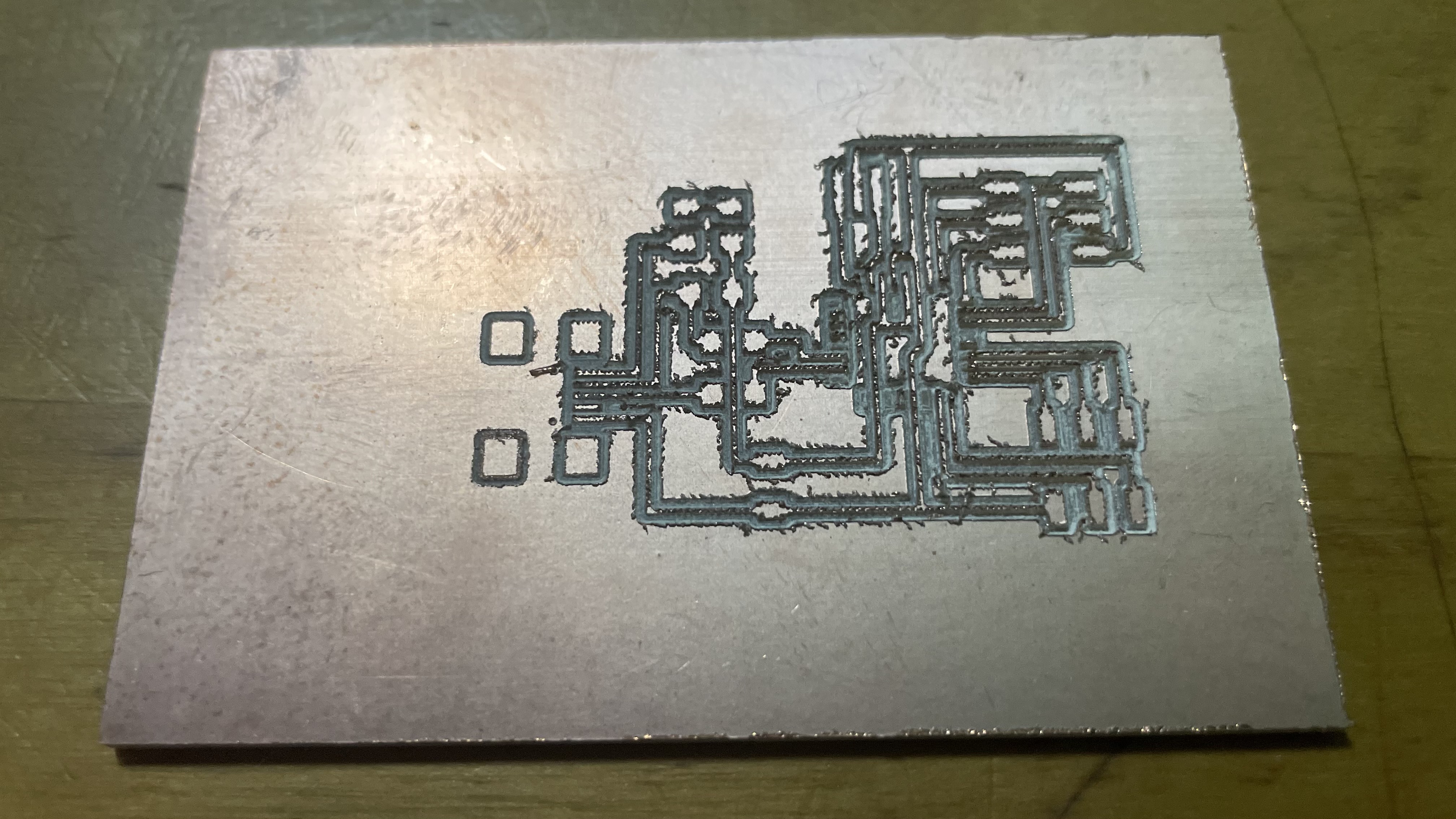
For all of these failed PCBs, some of them the drill was cutting to deep, causing the traces to not appear at all, while others the traces were too thin and had too much burr, causing it to be unable to be soldered on.
After painstakingly milling the PCBs again and again, I finally ended up with a decent looking one.
Soldering
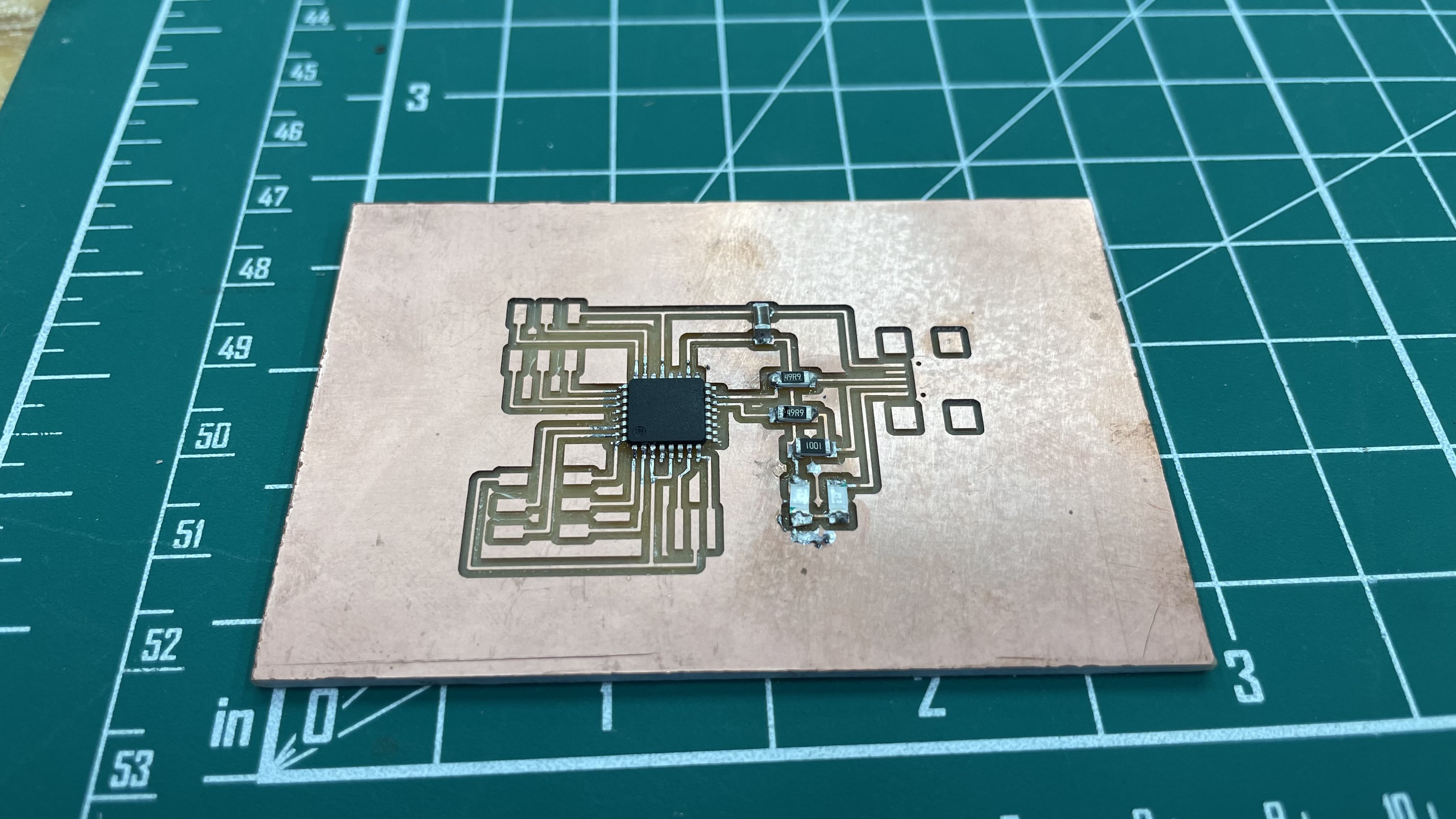
After the board was finally ready, it was time to solder on the components.
- These were the components I used:
- Atmega328/328p x1
- 1.5k ohm SMD resistor x1
- 49 ohm SMD resistor x2
- 10k ohm SMD resistor
- 10uF non-polar SMD capacitor x1
- 0.1uF non-polar SMD capacitor x1
- 2x3 ISP header x1
- 16MHz resonator x1
- 1N4148 diodes x2
Soldering was not that difficult for me, except for certain components which required much more precision and steady hands. I decided to solder on those components first. For the ATMega328, as it was really small and there were many pins to solder, soldering the first pins on was tough. I had to be precise when lining up the pins to the traces, which were also really tiny as well. After getting the first few pins soldered on, a method that my classmate Lynn taught me was to get enough solder for one row of pins onto the iron and then just spread the solder across all the pins. Of course, flux would have to be added first.
One of the previous boards where I had already solderd some components on had some critical errors that I overlooked. I only realised these mistakes a while after I soldered on the components, which left me no choice but to hardwire some of the connections if I did not want to mill a new board
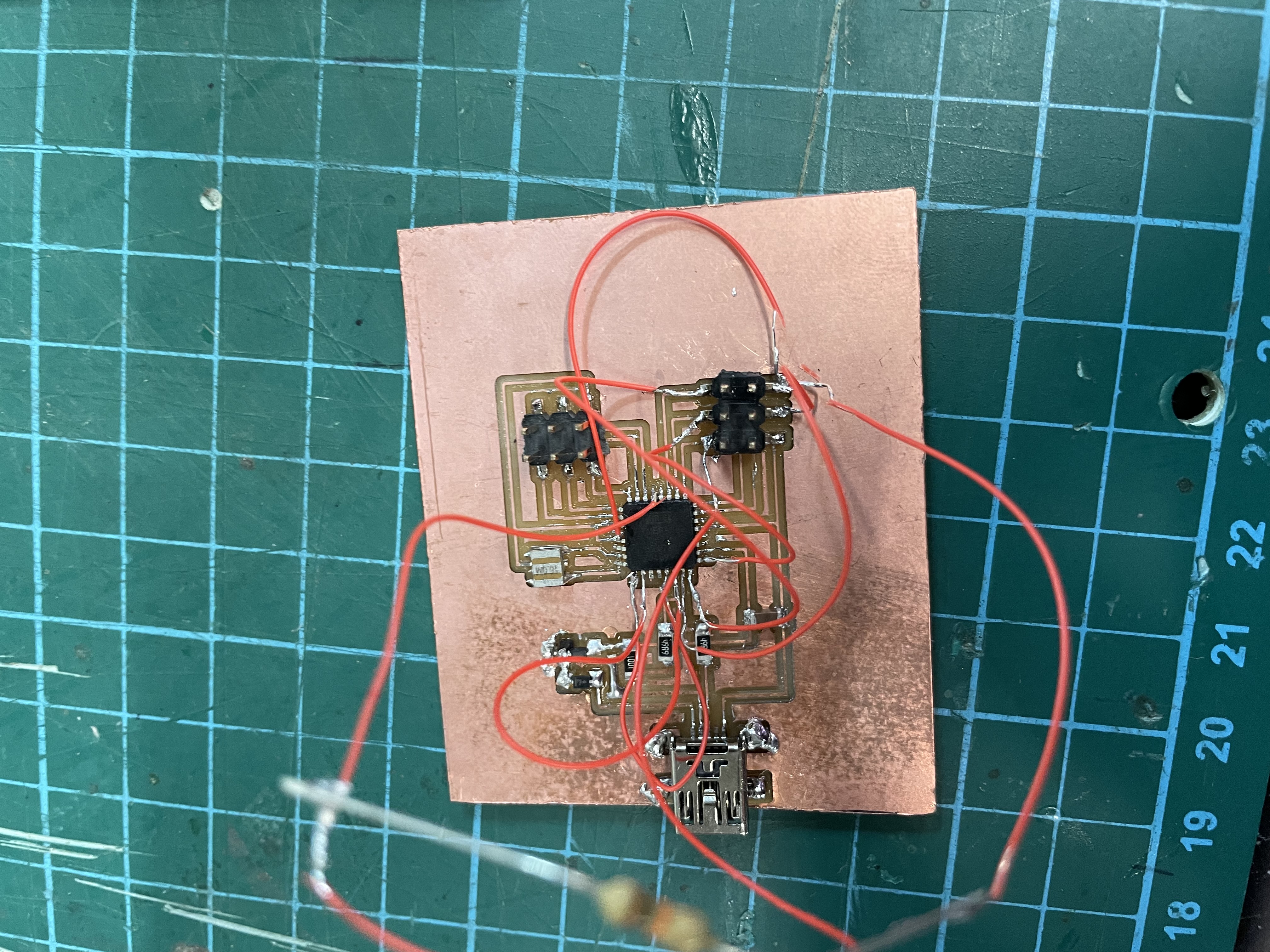
When checking for whether the board can even be detected by the laptop, there was something wrong with the connections and the board could not be detected. Despite my effort to try and salavge my board, it was to no avail. I had no choice but to cut a new board at this point. After cutting out a new board, the soldering of this board went smoothly and the components were mostly intact. However, despite several tests and trying to debunk the problem, the same problem persisted, which is that the USB device was not recognised. When checked with avrdude, the specifc signal for the Atmega328 was correct and the chip had no issues. This led me to suspect that it was something to do with the V-usb library. The board could be programmed as a normal Arduino, just not capable for usb purposes.